Manual Transmission Parts Diagram⁚ A Comprehensive Guide
This guide offers exploded views and parts illustrations for various manual transmissions. Manual transmissions comprise intricate components requiring expert knowledge for servicing. Diagrams aid in identifying parts for models like Dodge, GM, and Jeep T5 transmissions, offering repair assistance.
Manual transmissions, a cornerstone of automotive engineering, stand as intricate systems responsible for transferring engine power to the wheels. Unlike their automatic counterparts, manual transmissions require driver engagement to select gears, offering a direct connection to the vehicle’s performance. Understanding their inner workings is crucial for enthusiasts and technicians alike.
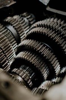
At their core, manual transmissions consist of numerous precisely engineered components working in harmony. Gears, shafts, synchronizers, and shift linkages all play vital roles in converting engine torque into usable force. These components are housed within a robust casing, designed to withstand the stresses of operation and protect the internal mechanisms.
This guide aims to provide a comprehensive overview of manual transmission parts diagrams, offering insights into the location and function of each component. By exploring exploded view diagrams, we can unravel the complexities of these systems and gain a deeper appreciation for their design and operation. Whether you’re a seasoned mechanic or a curious enthusiast, this guide will serve as a valuable resource for understanding manual transmissions.
Exploded View Diagrams⁚ An Overview
Exploded view diagrams are essential tools for understanding the intricate construction of manual transmissions. These diagrams present a disassembled view of the transmission, showcasing each component and its relative position within the assembly. By visualizing the spatial arrangement of parts, mechanics and enthusiasts can gain valuable insights into the transmission’s design and operation.
These diagrams typically depict each component separately, with lines or arrows indicating their location and orientation within the assembled transmission. This allows for easy identification of individual parts, such as gears, shafts, bearings, and synchronizers. Furthermore, exploded views often include part numbers and descriptions, facilitating the ordering of replacement components.

The use of exploded view diagrams is invaluable for disassembly, repair, and reassembly of manual transmissions. By following the diagram, technicians can systematically disassemble the transmission, noting the position and orientation of each component. During reassembly, the diagram serves as a roadmap, ensuring that each part is installed correctly and in the proper sequence. This meticulous approach minimizes the risk of errors and ensures the longevity and reliability of the transmission.
Input Shaft Components
The input shaft is a critical component in a manual transmission, serving as the primary conduit for transferring engine power into the gearbox. Understanding its constituent parts is essential for diagnosing and resolving transmission issues. Typically, the input shaft houses several key components, each playing a vital role in the transmission’s operation.
Firstly, gears are integral to the input shaft, often including first through fourth gears, along with a reverse gear, all meticulously integrated into the shaft’s design; A separate gear for fifth gear may also be present, pressed onto the input shaft’s end and secured behind a housing cover. These gears are responsible for providing various speed ratios, enabling the vehicle to accelerate and maintain speed efficiently.
Furthermore, bearings are essential for supporting the input shaft, ensuring smooth rotation and minimizing friction. These bearings are strategically placed to handle the loads and stresses generated during operation. Seals are also crucial, preventing lubricant leakage and protecting the internal components from contaminants. Proper maintenance and inspection of these input shaft components are vital for optimal transmission performance and longevity.
Output Shaft Components
The output shaft in a manual transmission is the crucial link transferring power from the gearbox to the vehicle’s wheels. This shaft is composed of several key components working in unison to deliver torque effectively. Understanding these components is vital for diagnosing and addressing transmission-related problems.
Gears are a primary part of the output shaft assembly. These gears mesh with those on the input shaft and countershaft, creating various gear ratios that dictate the vehicle’s speed and torque output; The output shaft also houses synchronizers, which are essential for smooth gear engagement. Synchronizers match the speeds of the gears before they engage, preventing grinding and ensuring seamless shifts.
Bearings support the output shaft, allowing it to rotate freely while handling the significant loads generated during operation. Seals are also critical, preventing oil leaks and protecting the internal components from contamination. A yoke or flange connects the output shaft to the driveshaft, transmitting power to the differential and ultimately to the wheels. Regular inspection and maintenance of these output shaft components are crucial for maintaining optimal transmission performance and vehicle reliability.
Gear Sets and Ratios
Gear sets and their corresponding ratios are fundamental to a manual transmission’s operation. These sets consist of multiple gears of varying sizes, strategically arranged to provide different speed and torque outputs. Each gear ratio represents the relationship between the input speed and the output speed, influencing the vehicle’s acceleration and fuel efficiency.
A lower gear ratio (e.g., 3⁚1) delivers higher torque multiplication, ideal for starting from a standstill or climbing steep inclines. Conversely, a higher gear ratio (e.g., 1⁚1 or overdrive) provides lower torque but higher speed, suitable for cruising on the highway and maximizing fuel economy. The selection of appropriate gear ratios is crucial in optimizing a vehicle’s performance characteristics.
Manual transmissions typically feature multiple forward gear ratios and a reverse gear. The driver selects these ratios manually using a shift lever, engaging different gear sets within the transmission. Understanding gear sets and ratios is essential for diagnosing transmission problems, selecting appropriate replacement parts, and optimizing vehicle performance based on driving conditions and requirements.
Synchronizer Mechanisms
Synchronizer mechanisms are crucial components within a manual transmission, enabling smooth and seamless gear changes. Their primary function is to synchronize the speeds of the gears being engaged, preventing grinding and damage during shifting. These mechanisms rely on friction to equalize the rotational speeds before the gears fully mesh.
A typical synchronizer consists of a synchronizer ring, a hub, a sleeve, and several small springs and keys. When the driver moves the shift lever, the synchronizer ring makes contact with the gear, applying friction to bring the gear’s speed closer to that of the output shaft. Once the speeds are nearly matched, the sleeve slides over the synchronizer ring and engages the gear, completing the shift.
Properly functioning synchronizers are essential for a comfortable and reliable driving experience. Worn or damaged synchronizers can lead to difficult shifting, grinding noises, and premature wear on other transmission components. Regular maintenance and timely replacement of worn synchronizers are vital to ensure the longevity and performance of the manual transmission. Exploded views of the synchronizer mechanism help to identify individual parts for repair.

Shift Linkage and Levers
The shift linkage and levers form the crucial connection between the driver’s gear selection and the internal mechanisms of the manual transmission. This system translates the driver’s movements at the shift lever into the precise engagement of gears within the transmission housing. A well-designed and properly maintained shift linkage ensures smooth, accurate, and responsive gear changes.
The shift linkage typically comprises a series of rods, cables, or a combination of both, connecting the shift lever to the transmission’s shift forks. Levers are used to amplify the driver’s input and provide the necessary force to move the shift forks, which in turn engage and disengage the gears. The design and complexity of the shift linkage can vary depending on the vehicle’s configuration and the transmission type.
Issues with the shift linkage, such as worn bushings, loose connections, or damaged cables, can lead to sloppy shifting, difficulty engaging gears, or even complete failure to shift. Regular inspection and maintenance of the shift linkage are essential to ensure optimal performance and prevent potential problems. Diagrams assist in correctly identifying the components.
Transmission Casings and Housings
The transmission casing, or housing, serves as the protective shell for all the internal components of a manual transmission. It is a robust structure designed to withstand the considerable forces and stresses generated during operation. Typically made of cast iron or aluminum, the casing provides structural rigidity and precise alignment for the gears, shafts, and other essential parts.

The housing also acts as a reservoir for the transmission fluid, which lubricates and cools the internal components. Proper sealing is critical to prevent leaks and maintain adequate fluid levels. The design of the transmission casing often includes features such as mounting points for the transmission to the vehicle’s chassis and provisions for attaching the shift linkage.

Damage to the transmission casing, such as cracks or fractures, can compromise the transmission’s integrity and lead to serious problems. Regular inspection of the casing for signs of damage is essential. Diagrams of the transmission casing help in identifying specific features and potential problem areas. Moreover, some diagrams show the housing cover and the fifth gear assembly.
Seals and Gaskets
Seals and gaskets are crucial components in a manual transmission, responsible for preventing fluid leaks and maintaining internal pressure. They are strategically placed throughout the transmission to seal joints between housings, shafts, and other parts. These components ensure proper lubrication and prevent contamination from external elements.
Various types of seals and gaskets are used in a manual transmission, including O-rings, lip seals, and paper gaskets. Each type is designed for a specific application and sealing requirement. Over time, seals and gaskets can degrade due to heat, pressure, and chemical exposure, leading to leaks. Leaks can result in reduced lubrication, overheating, and ultimately, transmission failure.
Regular inspection and replacement of worn or damaged seals and gaskets are essential for maintaining transmission health. Manual transmission parts diagrams often highlight the location and type of seals and gaskets used in a specific transmission model. These diagrams are invaluable for identifying the correct replacement parts and ensuring proper installation during repairs. Moreover, diagrams show the seal of the transmission shift lever shaft.
Common Manual Transmission Models
Numerous manual transmission models have been produced over the years, each with unique designs and applications. Some common models include the Borg-Warner T5, known for its use in various Ford and GM vehicles, and the New Venture NV4500, a heavy-duty transmission often found in Dodge trucks. The ZF S5-42 and S5-47 are other popular models used in Ford trucks and vans.
General Motors also produced several notable manual transmissions, such as the Saginaw 3-speed and 4-speed. These transmissions were widely used in GM cars and trucks. Each transmission model has its own specific parts and design characteristics. Manual transmission parts diagrams are essential for identifying the correct parts for each model.
Diagrams provide exploded views and detailed illustrations of the transmission’s internal components. These diagrams are invaluable for mechanics and enthusiasts working on repairs or rebuilds. Specific diagrams are available for various models, including the MT82 and T-56. Understanding the common manual transmission models and utilizing the corresponding parts diagrams is crucial for successful maintenance and repair.
Troubleshooting with Parts Diagrams
Parts diagrams are invaluable tools for troubleshooting manual transmission issues. When diagnosing a problem, a parts diagram can help identify the potential components involved. For example, if a transmission is leaking, the diagram can pinpoint the location of seals and gaskets that may need replacement.
Similarly, if a transmission is experiencing shifting problems, the diagram can help identify worn synchronizers, shift forks, or other related parts. The exploded views provided in the diagrams allow for a clear understanding of how the different components interact, making it easier to diagnose the root cause of the issue. By comparing the diagram to the actual transmission, mechanics can quickly identify missing or damaged parts.
Furthermore, parts diagrams often include part numbers, which is essential for ordering the correct replacement parts. Using a parts diagram during troubleshooting can save time and prevent costly mistakes. When tackling a manual transmission repair, always consult a parts diagram to ensure accurate diagnosis and effective repairs. This ensures that the right components are addressed, leading to a successful and long-lasting solution.
Resources for Manual Transmission Diagrams and Parts
Finding reliable diagrams and parts for manual transmissions is crucial for successful repairs and maintenance. Several online resources offer comprehensive parts diagrams for various transmission models. Websites specializing in manual transmission repair often provide exploded views and detailed parts lists, aiding in accurate identification and ordering.
Automotive forums and online communities can also be valuable resources. Enthusiasts and experienced mechanics often share diagrams, repair tips, and part sourcing information. Additionally, manufacturers’ websites and parts catalogs provide official diagrams and part numbers, ensuring accuracy and compatibility. Local auto parts stores and transmission specialists can also offer assistance in locating diagrams and sourcing parts.
When using online resources, it’s essential to verify the accuracy of the diagrams and part numbers. Cross-referencing information from multiple sources can help ensure you’re using the correct information. Furthermore, consider purchasing repair manuals that include detailed diagrams and step-by-step instructions. These manuals are specifically tailored to particular transmission models, providing valuable insights and guidance. By utilizing these resources effectively, you can confidently tackle manual transmission repairs and maintenance.